Concepts
Before going any further, let’s discuss some of the key concepts around BaseJumper base boards and agree on terminology that can be used when discussing the associated components.
Platform
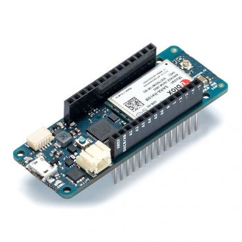
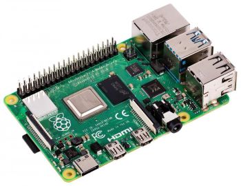
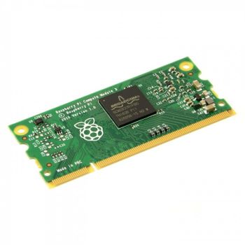
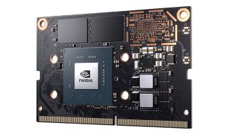
Arduino, Raspberry Pi, Raspberry Pi compute module, Jetson. Hopefully you’ve already heard of one or more of these and have some idea of what they are. But what would you call them, collectively? Single board computers? No, not all of them. System on module? Sure, some are. But there’s not really a name precisely captures them all. So, for better or worse, we’ve decided to call them Platforms.
The Platform typically runs your application code, which then controls the circuits provided by the base board. We’ll talk about base boards and circuits next, as they also have specific meanings.
Base Board
Shield, hat, cape, wing. Familiar with any of these terms? They are all “add-on” boards of sorts, that plug in to a platform to extend its functionality. They provide additional circuits, such as sensor & actuator interfaces, transceivers, onboard MEMs sensors, etc. A BaseJumper base board is similar to one of these add-on boards, but with a couple of important differences.
The first difference between base boards and other shields/hats/capes that you may be familiar with is that base boards aren’t stackable. You can’t physically plug multiple base boards into the same platform. Now, that doesn’t mean that you can’t use multiple base boards together. You absolutely CAN (pardon the pun). To link multiple base boards together we use CAN bus. This allows over 250 base boards to be connected to a single platform. The base boards don’t all have to be in the same location either. They can be distributed, so that they are situated close to the sensors and actuators that they interface to.
The second difference between a BaseJumper base board and shields/hats/capes is that base boards are cross-platform. A hat designed for a Raspberry Pi cannot be used with an Arduino. There are a couple of reasons why. First, the Arduino and the Raspberry Pi have different physical interfaces (headers are in different locations, with a different number of pins). Second, there is no guarantee that the Arduino will have the required peripherals to operate the shield. For instance the shield might need more PWM outputs than the Arduino can provide, or a I2S bus that the Arduino doesn’t have. Then there is the issue of porting the libaries that run under linux on the Pi to work on Arduino. BaseJumper base boards, on the other hand, are designed to be compatible with a range of different platforms. A jumper board is used to adapt between the physical interface of a particular platform to a common physical interface that is used across all base boards (more on this shortly). Communication between the platform and the base board requires only a SPI bus and a couple of GPIO pins - resources that are universal across all platforms.
If you’ve used shields, capes or hats a lot in the past, then you might be accustomed to stacking multiple boards together to get the functionality you require. Typical add-on boards are quite specialized and only do one thing. For example, they might just add some extra analog inputs, or drive a motor, or add a CAN interface. But not all of these things at once. BaseJumper base boards are quite different in this regard. BaseJumper boards aim to cram everything you need into a single board. They offer a mix of circuits and interfaces, so you can build up a complete system from one board. They also take care of providing a clean, regulated power supply to power your platform. In short, BaseJumper base boards provide a lot more functionality than your typical shield.
Jumper Board
All BaseJumper base boards have the same standard physical interface. The interface is made up of a footprint with 63 surface mount pads arranged in two rows. So how does, say, a Raspberry Pi with its dual row 40-pin header connect to the surface mount pads on the base board? The answer is jumper boards. Jumper boards are PCBs that adapt between the 63-pin footprint on the base board, and the physical interface of the platform (whether it be dual row headers, castellated edges, a SODIMM module or something else). Jumper boards have castellated edges that are soldered to the pads on the base-board, providing a compact and low-profile interconnect. In the case of the Raspberry Pi, the jumper board has a dual-row 40 pin socket to mate with the header on the Pi, plus some mounting posts for securing the Pi in place. There is a separate jumper board for every supported Platform with the appropriate sockets/connectors/interconnects for the specific platform.
Jumper boards may also have electronic components mounted to them. For example, the Raspberry Pi doesn’t have its own CAN controller, so we provide the option of mounting a CAN controller IC to the jumper board. Another example: Arduino Uno is still rocking old-school 5V GPIO pins, so there are level-shifter ICs on its jumper board to translate between 5V and 3.3V.
Full Footprint and Half Footprint
We just talked about the standard 63-pin footprint which is used to connect base boards to jumper boards. This is called the full footprint and its physical size is about 64x73mm. There is also another variant called the half footprint. It has 31 pins, and is (you guessed it) roughly half the size. Half-footprint jumper boards are available for platforms that have a small physical form-factor, such as the Arduino MKR series. Half-footprint jumper boards can be used with any base board, regardless of whether it has a full or half footprint interface. When using a half footprint jumper on a base board with a full footprint, the jumper is soldered to the lower half of the footprint (the first 31 pins) and the remaining pins (32-63) on the base board are left unconnected. Half footprint jumpers can be used with half footprint base boards to provide a very compact solution for smaller systems that do not require a lot of IO.
Circuits
RS485 transceiver, quadrature encoder interface, GPS, MEMs accelerometer, high-side driver. These are just a few examples of functionality that can be provided by a base board. We refer to these as Circuits. Each circuit is comprised as some physical components on the baseboard as well as the firmware drivers to operate the hardware. An analog input circuit, for example, has physical components for noise filtering, protecting against transients and amplification. Then there are firmware drivers that operate the ADC on the microcontroller, check for fault conditions and optionally perform additional signal conditioning.
The circuit drivers take care of the tricky low-level stuff and anything that is timing critical. These details are encapsulated, and a simple API is presented to allow the circuit to be easily operated without worrying about things like interrupts, race conditions, buffer overflows, clock generation, register configurations, etc.
Conclusion
The platform is whatever single-board computer/system-on-module/development board you select to run your application. An example that many people are familiar with is a Raspberry Pi, but there are others to choose from too. BaseJumper base boards extend the functionality of the platform with circuits. Circuits allow you to connect to other real-world devices, such as sensors, actuators or communication buses. They could also be a sensor that is physically mounted to base board itself, such as an accelerometer, barometric pressure sensor or GPS. Base boards include all the firmware required to handle the low-level operation of the circuits. Circuits can be controlled from an application running on the platform by installing a library that provides an easy-to-use API. A jumper board sits between the base board and the platform to adapt the physical interface.