CAN Bus
Controller Area Network (CAN) is a communication bus used widely in automotive, argicultural, mobile and industrial equipment. It is well known for providing reliable communications in noisy enviroments. Many devices are able to be connected to a single CAN bus. It has built-in mechanisms for handling collisions when multiple devices try to transmit simultaneously.
Wiring
To get the best performance out of CAN bus you will need to use suitable cabling. CAN drivers have a differential output. The differential output provides excellent rejection of common-mode noise/interference - but only when used with a twisted pair. So, as a minimum - make sure your data wires are twisted.
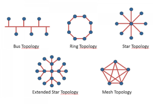
CAN should wired in a bus topology. There should be a single central cable (called the bus) running through the system, with just short cables (called stubs) connecting each device to the bus. As a rough rule of thumb, keep the stubs length less than 30cm in length for 1Mb/s. The aim is to minimise the impact of signal reflections. Reflections occur when the signal reaches the end of an unterminated transmission line and then bounce back, causing interference.
It’s a good idea to use shielded cable if you’re doing long runs, high data rates, operating in a paricularly noisy environment, or concerned about electromagnetic emissions. There is cable available that is specifically suited to CAN. It will contain a shielded twisted pair for the data, and often comes with an additional twisted pair of thicker wires for distributing power. Here is an example.
Termination
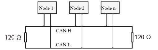
Terminating a CAN bus is essential. Without proper termination, reflections will occur when signals reach the end of the bus. The signal will bounce back and forth along the bus, causing interference. To terminate the bus, place a 120ohm resistor between the two data lines at each end of the bus. The location of the resistors is important - be sure to place them at each end of the bus near the first and last devices. Proper termination will stop those nasty reflections, giving you a nice clean signal.
Some CAN devices come with termination resistors built-in. BaseJumper base boards have a space on the PCB for termination resistors. The boards are shipped without the resistors, but they can be fitted if needed. This saves having to insert a resistor in the harness. There are also connectors available which have CAN termination resistors built-in.
To check if your bus has the right number of terminating resistors, you can use a multimeter to measure the DC resistance between the two data wires. If everything is correct you should measure around 60 ohm (two 120 ohm resistors in parallel). If it’s less, you have too many resistors. If it measures 120 ohm or open, you have too few.
Isolation
Isolation is sometimes needed if the device you are communicating with has a different ground reference to the base board. This situation arises if the remote device is not powered from the same power supply as the base board, or if there are long cable lengths between devices. In these situations you should select a base board with galvanically isolated serial circuit. In addition to the data lines, isolated circuits will have an additional pin for a ground reference. Connect this to the ground of the remote device you are communicating with. Once this is connected up, the communications will work even if ground potential of the remote device is different to the base board.
Usually the requirement for isolation can be avoided by connecting together the grounds of all of the components in the system. Note that there is no harm in using an isolated serial circuit even if it’s not strictly required. An isolated circuit will work just fine in all scenarios, provided you remember to wire up the ground reference.
Refer to the documentation for your specific base board to see if a CANBus instance is isolated. If your base board has other isolated communication circuits such as RS485, keep in mind that they may share the same isolated supply.
Protocols
BaseJumper base boards provide the CAN physical layer, and an API for reading/writing raw packets of data from/to the bus. Chances are, you will need a layer of software on top of this to implement a protocol. A protocol describes how the information is organized in the packets that are sent over the CAN bus. CANOpen and SAE J1939 are two examples of popular protocols. For simple applications, it is also possible to roll-your-own protocol. The task of selecting and implementing a protocol is left up to you.
Direct Control
When direct control is selected, the CAN controller on the base board is disabled and the transciever is connected directly to the platform. This allows the platform to use the CAN bus directly (without using the CAN controller on the base board as an intermediary).
If your platform does not have a can controller (many don’t), there will likely be an option on the jumper board for fitting one. The first step is to purchase the appropriate CAN controller IC and solder it on (refer to the page for your specific platform for more details). Next, you will need to install the libraries on your platform that will communicate with the CAN controller over SPI. You will then be ready to enable direct control on the base board and start using the bus.
Direct control can be useful in scenarios where you want to make use of existing libraries to implement a CAN protocol, without having to reconfigure the library to use the BaseJumper CAN API.
Not all CANBus circuit instances offer direct control. There is an API function available to check if a particular instance supports direct control.
CAN FD
BaseJumper boards have full hardware support for CAN FD. Some CAN FD features are also supported in software. The software supports speeds beyond 1MB/s, and payload lengths up to 64 bits. The software does not currently support dynamic changing of transmission speeds. Of course, BaseJumper boards will also work just fine on CAN 2.0 networks.
Hardware Customization
This section describes the customizations that can be made to the base board’s hardware. Only general information is provided here. Component designators and board assembly drawings can be found on the boards page for a specific base board.
Termination
Provision is provided for on-board terminating resistors. A split termination scheme is used for improved EMC performance. Split termination uses two 60ohm resistors in series instead of a single 120ohm resistor.
| Component Name | Description |
|---|---|
| Rterm1 | Upper termination resistor |
| Rterm2 | Lower termination resistor |
Software
Initialization
Before using CAN bus, you must create a circuit handle and call the start function to start the bus. The start function accepts a baud rate and a boolean to indicate if CANFD functionality will be used.
#include <BaseJumper.h>

using namespace BaseJumper;

CanBus::Handle can(0);

void setup()
{
    basejumper_init();
    can.create();
    can.start(CanBus::Baud::_125K, false); // connects to the can bus with baud 125Kb/s and CAN FD disabled
}
Transmitting
All messages transmitted over CAN have an associated identifier. The identifier can be either 11-bits (standard) or 29-bits (extended) long. Transmitting a message is pretty simple. You construct a message object containing both the identifier and the data (payload). CAN allows for the length of the payload to vary, so you must also specify the payload size. The message object is then passed to a write function.
    // create data message
    CanBus::Msg<3> msg; // creates a message object, which can hold 3 bytes of data (at most).
    msg.id = CanBus::Id::std(0x012); // assigns a standard identifier
    msg.data.items[0] = 0x01; // assign data
    msg.data.items[1] = 0x02;
    msg.data.items[2] = 0x03;

    // send it
    can.write(msg);
To send a remote transmission request (RTR), the is_rtr field on the message object should be set, and the data left unassigned.
    // create rtr message
    CanBus::Msg<0> msg;
    msg.id = CanBus::Id::std(0x012); // ID of the message to request
    msg.is_rtr = true; // set RTR flag
    msg.data_len = 2; // expected length of message

    // send rtr message
    can.write(msg);
If writing a message to the bus fails due to a NACK, arbitration failure or bus error, the controller will automatically try to send it again.
Receiving
Before you can start receiving CAN messages, you must configure a filter. A filter selects which messages you want to recieve, based on the message’s identifier. A filter is defined using an identifier plus a mask. For a message to be accepted, it must have an ID that matches the filters ID for all bits where the bit-mask is set to 1.
Filters are registered using the add_filter function. This function returns a handle to the filter (with type FilterId), which you should assign to a variable. You will later use this filter handle to retrieve messages, or to remove the filter.
CanBus::FilterId filt_id;

void setup()
{
    // register filters after can bus has been started

    /* Set up a filter to catch all messages with an extended identifier  *
     * ending in 0xABC. Maximum expected message length is 8.             */
    filt_id = can.add_filter(CanBus::Id::ext(0xABC), 0xFFF, 8);
}
It is possible to set up multiple filters. If a message matches more than one filter, it will only be captured by the first filter it passes. If you want to catch all messages on the bus, then you can use a single filter that accepts all messages by specifying a mask of 0.
To check for messages, use the available function. To read messages use the read function. Both take a filter id as an argument. Before accessing the message data, be sure to check that it is not an RTR frame (field is_rtr), and check the actual length of the data (field data_len).
void loop()
{
    // check how many messages are available
    auto msg_count = can.available(filt_id);
    while (msg_count > 0)
    {
        // read a message
        auto msg = can.read<8>(filt_id);

        char str[100];
        if (msg.is_rtr)
        {
            sprintf("rtr frame with id: %u, len: %u", msg.id, msg.len);
            // this is an rtr frame. don't try use msg.data.items
        }
        else
        {
            sprintf("data frame with id: %u, len: %u, byte0: %x", msg.id, msg.len, msg.data.item[0]);
            // this is a data frame. go ahead and access the data in msg.data.items.
        }
        msg_count--;
    }
}
Each filter has an associated buffer for holding received messages. When a message is read, it is removed from the buffer. If the application code does not check for messages frequently enough, then the buffer may fill and messages will be discarded.
API
specs
Specs specs()
Gets the specifications for a CAN Bus circuit instance.
Returns a Specs data structure with the following fields;
| Type | Name | Description |
|---|---|---|
bool | has_direct_control | true if instance supports direct control |
uint8_t | max_filts | maximum number of filters |
uint8_t | max_msg_per_filt | maximum number of messages for each filter |
uint16_t | max_data_per_filt | maximum total bytes of data for filter |
data structures
CanBus::Id
Holds CAN message ID, and its type (standard or extended)
Use CanBus::Id::std(uint32_t val) to create a standard 11-bit ID.
Use CanBus::Id::ext(uint32_t val) to create an extended 29-bit ID.
| Type | Name | Description |
|---|---|---|
uint32_t | value | id value |
CanBus::Msg<uint8_t max_len>
Holds a single CAN frame.
The max_len compile-time parameter is the maximum data length of the message (used to allocate storage). For standard CAN 2.0 messages, the payload size only goes up to 8, so max_len can be 8. CANFD messages can hold up to 64 bytes of data, so choose max_len according to the actual message size you are using.
The structure has the following fields;
| Type | Name | Description |
|---|---|---|
CanBus::Id | id | message id |
bool | is_rtr | true for RTR frame, false for data frame |
uint8_t | data_len | actual length of data (or requested data in case of RTR) |
uint8_t[max_len] | data.items | standard c array holding the data |
connecting
void start(CanBus::Baud baud, bool use_fd)
Brings the CAN bus online.
baud specifies the bus baud rate. 125 kbit/s & 250 kbits/s are most commonly used. The maximum speed for CAN 2.0 is 1MB/s. Speeds above that are for CANFD only. Supported bauds are;
CanBus::Baud::_125K
CanBus::Baud::_250K
CanBus::Baud::_500K
CanBus::Baud::_1M
CanBus::Baud::_2M
use_fd specifies whether support for CANFD should be enabled.
void stop()
Stops the CAN bus.
configuring filters
CanBus::FilterId add_filter(CanBus::Id message_id, uint32_t mask, uint8_t max_data_len)
Adds a filter for receiving incoming data/RTR frames.
message_id is an example id for the messages to be received.
mask is a bitmask for the id. Any bits in the incoming message ID with a corresponding 1 in the bitmask must match the corresponding bit in message_id to pass the filter.
Returns a filter handle. If there are no remaining filters available then CanBus::invalid_filter_id is returned.
void remove_filter(CanBus::FilterId filter_id)
Removes a filter.
filter_id is the handle of the filter that was returned by a prior call to add_filter.
reading
size_t available(CanBus::FilterId filter_id)
Checks if there are messages available to read for a particular filter.
Always check this before calling read.
Returns the number of messages available to be read using the read function.
template <uint8_t max_len>
CanBus::Msg<max_len> read(CanBus::FilterId filter_id)
Reads a CAN message for the given filter.
Before calling this function, make sure you have a valid filter handle (obtained by calling add_filter) and that there are messages available for that filter (using available).
max_len is a compile-time argument specifying the maximum expected data length. It is used to allocate space to store the data.
writing
template <uint8_t max_len>
void write(CanBus::Msg<max_len> messsage)
Writes a message to the bus.
max_len is a compile-time argument specifying the maximum expected data length. It is used to allocate space to store the data.
message is the can message to be written to the bus.
status
CanBus::Status get_status()
Returns an enum indicating the CAN Bus circuit status.
| Value | Description |
|---|---|
CanBus::Status::Ok | Indicates there have been no errors |
CanBus::Status::RxOverflow | Receive buffer for one or more of the filters has overflowed |
CanBus::Status::TxOverflow | Transmit buffer has overflowed |
The status is latched. It will only return to Status::Ok after reset_status is called.
void reset_status()
Clears the status.
Status is returned to Status::Ok.
direct control
void enable_direct_control(bool val);
Enables/disables direct control by the platform
Direct control is enabled if val is true.
Direct control is disabled if val is false.
Direct control is disabled by default.
bool direct_control_enabled();
Checks if direct control by the platform is currently enabled.
Returns true if direct control is enabled.
Returns false if direct control is disabled.